TruResolution Objectives Maximize Resolution in Deep Imaging
TruResolution objectives feature an automatic spherical aberration compensation system designed for deep observation
Designed for use with the Olympus FVMPE-RS multiphoton laser scanning microscope, TruResolution objectives are equipped with a computer-controlled correction collar system that can automatically adjust to compensate for spherical aberration during deep observation of thick samples. When imaging deep within a sample using a multiphoton microscope, spherical aberration reduces fluorescence intensity and resolution. An objective correction collar can help alleviate this issue; however, manual correction collars can be cumbersome to operate. With the TruResolution system, dedicated software drives a motorized correction collar using Olympus’ unique algorithm, determining the optimum collar setting at each depth, quickly and accurately. For deep Z stack image acquisition in particular, the correction collar is automatically adjusted as you observe progressively deeper into the sample. As a result, the performance of TruResolution objectives can be maximized for all depths to acquire bright and high-resolution images.
Spherical aberration and the role of correction collars
Microscope objectives rely on precise design and rigorous manufacturing processes to attain the high level of optical performance necessary to resolve fine structures within cells and organelles. A single spherical lens is physically limited in its ability to focus light to a sharp point. Thus, objectives are designed from combinations of multiple lens elements that have been carefully selected and positioned to precisely balance out individual optical aberrations that would distort or blur the formation of an image. However, changes in refractive index due to the immersion media, cover glass, or the specimen itself can upend this balance. Light rays coming from the periphery of the objective aperture approach the focus at a larger angle, and thus experience greater refraction at an interface than rays coming from the center of the objective. This results in spherical aberration, where the focus position differs in depth between the central and peripheral light rays, and manifests as lower resolution and fluorescence intensity in a microscope.
Objectives can be designed to compensate for spherical aberration, but the appropriate amount of correction will vary with observation conditions. An adjustable correction collar provides the flexibility needed to maintain imaging performance across a range of conditions. For example, a water dipping objective with a correction collar is set at 0 when the microscope is focused in water and there is no variation in refractive index (Fig. 1(a)). However, when the surface of a tissue specimen is observed through a glass cover slip, refractive index changes due to the layer of glass introducing spherical aberration that degrades the focus (Fig. 1(b)). This spherical aberration can be compensated by advancing the correction collar to realign the focal points of the light rays (Fig. 1(c)). If the focal plane is moved deeper into the sample, more spherical aberration is introduced, and the previous collar setting is no longer sufficient to maintain a sharp focus (Fig. 1(d)). The setting must be adjusted further. With multiphoton microscopes, observation depths can reach from several hundred micrometers to several millimeters and spherical aberration correction becomes even more critical to maintaining high image resolution and contrast.
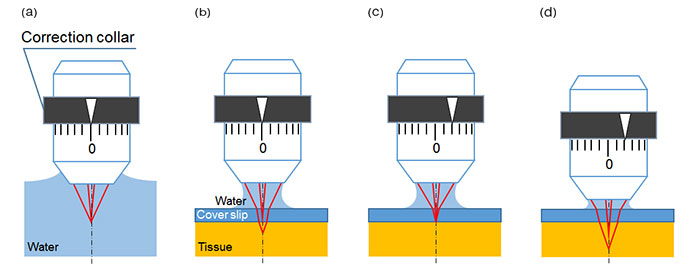
Figure 1: Schematic figures of spherical aberration caused by cover glass or tissue and the effect of correction collar adjustment.
(a) Ideal focus point—When a water-dipping objective is used to observe an object in water, axial light and off-axial light focus at the same point. There is no spherical aberration effect.
(b) Focus point with spherical aberration—When the surface of tissue is observed under a cover glass with water immersion, refraction happens at both surfaces of the cover glass, which causes spherical aberration.
(c) Spherical aberration is compensated by the correction collar adjustment.
(d) With the correction collar still set at the adjustment setting in Fig. 1(c), spherical aberration occurs again when the focus position is moved to a deeper position within the sample.
Automatic compensation of spherical aberration with the TruResolution system
In multiphoton laser scanning microscopy, both image resolution and image contrast are strongly dependent on the focal spot size. A smaller, tighter focus directly translates to higher resolution, but also leads to higher light density and more efficient multiphoton excitation. Thus, higher fluorescence intensity is delivered for the same total laser power. Proper adjustment of an objective correction collar helps minimizes spherical aberration to maintain a sharp focal spot. However, the optimum position of the correction collar differs depending on the refractive index of the sample, the thickness of the cover glass, and the depth of the observation plane. It is sometimes necessary to adjust the correction collar multiple times while acquiring images.
Setting a manual correction collar during image acquisition can be problematic because each adjustment slightly shifts the focal plane (Fig. 2(a)). Additionally, multiphoton microscopy is often performed in a darkroom environment, exacerbating the difficulty of manually operating the correction collar. These issues make it particularly challenging to optimize collar settings during volume image acquisition. Most multiphoton microscopes must settle for an intermediate collar position that is appropriate at one plane of the Z-stack, but less than optimal at most other planes.
Olympus TruResolution objectives solve these problems with a computer-controlled motorized correction collar system. Actuation of the collar is automatically coordinated with the microscope focus motor, adjusting the objective Z-position to maintain a consistent focal plane even when the correction collar is rotated (Fig. 2(a)). Remote control via software not only simplifies direct user operation, but also enables automated collar adjustment at every plane during Z-stack acquisition. Three-dimensional images can be acquired with improved resolution and contrast, particularly during deep observation.
The TruResolution system employs a customized algorithm that determines the optimum correction collar position based on a contrast curve derived from images acquired at different collar settings (Fig 2(b)). A user can perform this search automatically with a single click in the dedicated software. Further, by finding and saving the best correction collar position at each plane, the TruResolution system can drive the correction collar automatically throughout a volume scan. This innovative function simplifies the acquisition of consistently bright and high-resolution images at every depth.
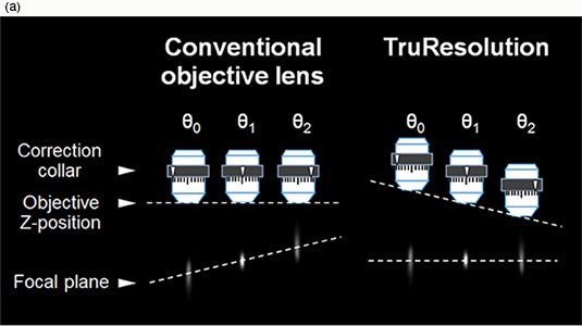
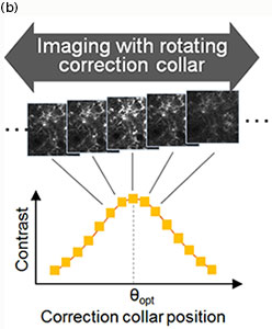
Figure 2
(a) When conventional objectives collars are rotated, the focal plane also changes (left). TruResolution objectives maintain the focal plane by automatically changing the Z position of objective according to the rotation angle (right).
(b) Finding the optimum correction collar angle (θopt): A contrast curve is determined by calculating the contrast value of each acquired image at different correction collar angles. The optimum correction collar position is calculated by determining the peak of this contrast curve.
Deep imaging applications
Figure 3 demonstrates the powerful deep imaging capabilities of TruResolution objectives using fluorescent beads embedded in a gel with a refractive index and light scattering coefficient similar to those of a live mouse brain. The bottom row of images shows the gradual degradation of the focal spot as the observation region is advanced from the top of the sample, down to 800 mm deep, without adjusting the correction collar. Notable is the smearing of the images along the z-axis and decrease in peak intensity with depth. In contrast, automatic collar adjustment using the TruResolution system delivers a more consistent compact focal spot across the different depths. The top row of images clearly shows how TruResolution improves image brightness and resolution during deep imaging.
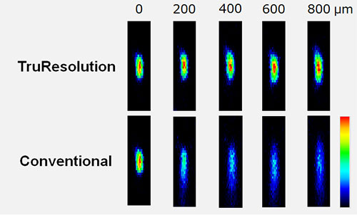
Figure 3
Fluorescent microbeads (diameter = 200 nm) in a gel with optical characteristic similar to live mouse brain (refractive index: 1.36, light scattering coefficient: 43 cm-1) excited at 960 nm with constant laser power used for all images .
(upper row) Microbead XZ images acquired at different depths using TruResolution automatic spherical aberration compensation.
(lower row) Microbead XZ images acquired at different depths using a fixed correction collar initially adjusted for optimal imaging at the surface of the gel.
Image brightness scales are normalized at each depth. All the images were acquired with the FV30-AC25W objective.
Figure 4 shows a practical application of TruResolution for in vivo observation of neuronal dendrites in a live mouse brain. These images were acquired 400 µm below the brain surface using the FV30-AC25W TruResolution objective (25x magnification, 1.05 numerical aperture, 2 mm working distance). TruResolution spherical aberration compensation delivered a prominently brighter image than that acquired using a fixed correction collar. More importantly, structural morphology of submicron features such as dendritic spine heads and necks are more clearly captured when using TruResolution.
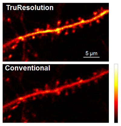
Figure 4: In vivo observation of neuronal dendrite in a live mouse brain (Thy1-YFP-H mouse, sensory cortex) acquired at 400 µm depth, with excitation at 960 nm.
(top image) Automated spherical aberration compensation by the FV30-AC25W TruResolution objective yields sharp, high-contrast images of dendritic spines.
(bottom image) For comparison, the same field of view was captured with the correction collar optimized for the sample surface – as is typical with conventional correction collars.
The TruResolution system is also effective with cleared tissue samples. Refractive index varies greatly between different tissue clearing techniques and may even vary between applications of the same technique. Attention to the correction collar position is vital to capturing consistently high image quality throughout the large volumes typically captured in cleared tissue. The FV30-AC10SV TruResolution objective (10x magnification, 0.6 numerical aperture, 8 mm working distance) is designed to accommodate refractive indices ranging from 1.33 to 1.52 and supports a range of tissue clearing methods. Figure 5 shows images acquired from a mouse brain cleared using ScaleA2. TruResolution was used to automatically determine the optimum collar setting and yielded sharp images with bright contrast throughout the volume, particularly when compared to images captured with an arbitrary collar position. Figure 5(b) exemplifies the considerable improvement in image resolution and brightness possible when TruResolution is used to minimize spherical aberrations.
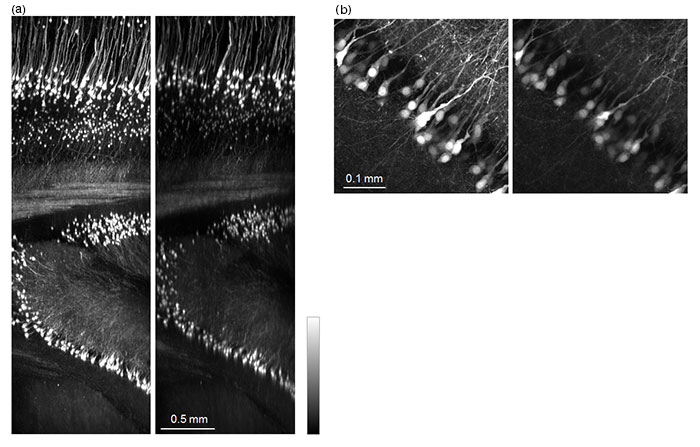
Figure 5: Mouse brain (Thy1-YFP-H mouse)cleared with ScaleA2.
(a) XZ image of a 4 mm Z stack: image on the left was acquired by the TruResolution system; image on the right was acquired using an arbitrary correction collar position.
(b) Maximum projection of XY images from 100 µm thickness at a depth of 2.7 mm:
image on the left was acquired by the TruResolution system; image on the right was acquired using an arbitrary correction collar position.
All the images ware acquired with 960 nm excitation at the same laser power and using the FV30-AC10SV objective.
Summary
These deep imaging results demonstrate how automated computer control of a motorized correction collar can improve multiphoton imaging under a variety of challenging observation conditions. TruResolution objectives enable the capture of bright, high-resolution 3D images by minimizing spherical aberration in a multiphoton microscope.
Author
Atsushi Doi
R&D Group
Optical Technology R&D Dept.
Optical System Development Div.
Olympus Corporation
Acknowledgments
Application images were acquired at the RIKEN BSI-Olympus collaboration center, courtesy of Dr. Hiromu Monai, Dr. Hajime Hirase, and Dr. Atsushi Miyawaki.
Reference
For more details on the studies mentioned in this whitepaper, please refer to the following article:
“A spherical aberration-free microscopy system for live brain imaging.” Biochemical and Biophysical Research Communications (BBRC), April 2018
Yoshihiro Uea, b, Hiromu Monaia, c, Kaori Higuchia, b, Daisuke Nishiwakia, b, Tetsuya Tajimaa, b, Kenya Okazakia, b, Hiroshi Hamac, Hajime Hirasec, Atsushi Miyawakia, c, d,
a BSI-Olympus Collaboration Center, RIKEN, Hirosawa, Wako-City, 351-0198 Saitama, Japan
b OLYMPUS Corporation, Hachioji-City, 192-0033 Tokyo, Japan
c Brain Science Institute, Center for Brain Science, RIKEN, Hirosawa, Wako-City, 351-0198 Saitama, Japan
d Center for Advanced Photonics, RIKEN, Hirosawa, Wako-City, 351-0198 Saitama, Japan.
对不起,此内容在您的国家不适用。